


The sockets are wired in series 2-2, 3-3, 4-4, 5-5 (using 4 wire).
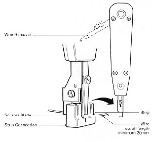
The connections on the sockets are Insulation Displacement Connectors (IDC). The wires, complete with insulation, are forced into the IDC slot using a special wire insertion tool (Inserter Wire No. 2a). The picture to the right shows the correct way to terminate a wire - note the wire is NOT stripped. Do not connect more than 2 wires to each connector (the third will normally fall off as you screw the face plate back on!).
Tip: Cut back the cable sheath about one inch and locate a nylon draw string. Pull this draw string and split the cable sheath for about five inches and then remove the sheath exposing the wires. Fix the cable to the socket using the cable strap supplied, then wrap the wires a couple of times around the socket housing in the middle of the socket and then fan out the wires and terminate. This leaves some spare in the wiring in case of maintenance.
Only use white sheathed telephone cable for internal use - black sheathed should be used externally.
The wiring should be connected to sockets using the following colours:
2 - Blue/white
3 - Orange/white
4 - White/orange
5 - White/blue
If six wire cable is used the Green wires can be connected as follows (these are not used but should be terminated):
1 - Green/white
6 - White/green
If an extension bell is fitted then this must be a 4000 ohm magneto type and should be wired to 3 and 5 on any socket.
Each telephone cable is terminated with a Plug No. 431A which has a latch on the right.
Some system phones have a latch on the left to stop people inadvertently plugging them into non-system extension sockets. The telephone lead is flat to fit into the plug. A special tool is required to connect the plug and cable together.
Plug No. 431A is used with 4 wire cordage, whilst Plug No. 631A is used with 6 wire cordage.
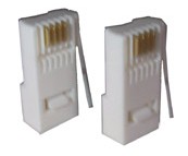
Do not attempt to connect the old style round telephone lead to a Plug No. 431A or 631A.
CORD WIRING
BT supplied cords came in differing styles. The common ones are tabled below.
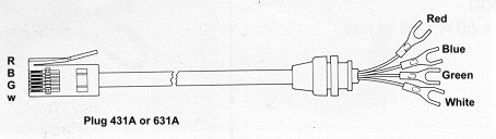
This is the normal colour code on BT supplied cords (Cord 4/502 shown).
Cord 4/500
Straight cord Plug ended at both ends
Used on Ambassador telephones, etc
Cord 4/502
Straight cord plug ended at one end and spade connections at other
Used on telephones with screw terminations
Cord 4/503
Curly cord with plug at one end and spade connections at other
Used on Ambassador handsets
BT - PLUG AND SOCKET TELEPHONES
Around 1979 Post Office Telecommunications introduced the Plug and Socket (PST) method of connection. This document explains how the concept works.
700 type telephones always had their bells or tone ringers connected in series (max of four) and this system needed four or five wires to each phone as the bell circuit, itself, used two wires. Each bell ringer was 1000 ohms.
PST changed this by making telephones work in a three wire system that allowed for the disconnection or reconnection of phones without causing interruption of the ringing circuit. The Plan 4 (old style plug and socket - Plug No. 420 ) arrangement involved the use of special sockets and specially wired telephones when more than one telephone was used.
PST changed all this in so much that telephones could be removed without interfering with other telephones.
The system starts with a master socket and this contains a capacitor (dc blocking for the bell circuit), a resistor (allows the network provider to test the line and ascertain whether the line is alright even though every telephone may be unplugged) and a gas discharge tube (transient voltage surge protector). The resistance of each telephone bell is now 4000 ohms.
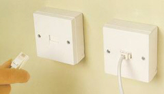
Every additional socket is a secondary/extension socket and contains no electrical components whatever (there can be as many extensions as one wants). The extension sockets are wired to the master socket in parallel.