


ISDN a basic Guide
ISDN ' Integrated Services Digital Network'
B Channels:
One ISDN line has two completely separate bi-directional 64kbit/s data circuits. Therefore from point X you can open one 64kbit/s circuit to point Y and at the same time have another completely separate 64kbit/s circuit from point X to point Z.
These individual 64kbit/s bearer circuits are commonly called 'B' channels and as there are two of them they are called B1 or B2.
On the modern and the now standard ISDN2E lines an incoming or outgoing call could end up on either one of these B channels.
On one configuration of an old style ISDN2 line an individual B channel was specific to a dial-in ISDN number.
Pieces of equipment can normally be set to make outgoing or accept incoming calls on any B channel or to be forced to just using one of the B channels.
CODEC (Coder Decoder):
For broadcasting audio down ISDN lines a Codec is needed. A Codec takes an audio signal and turns it into a digital signal; at the same time it compresses the signal so that all the digital bits will fit down a data (ISDN) line. A codec will also receive compressed data, uncompresses it and turn it back into an audio signal.
When compressing the audio a codec passes the data through a compression algorithm that is a clever device that works how to make the audio signal fit down a specific data link. It is imperative that the other end of the data link has an identical algorithm, which can decompress the data back to an audio signal.
There are many different algorithms available, by far the most common are G722, MPEG Layer2 and APTX. Each has different properties with advantages and disadvantages.
Category 5:
It is common in modern office buildings for a catagory 5 structured wiring system to be in place for use as a local area network (LAN) for computers, telephones etc. If a cat 5 structured wiring system is used for routing ISDN then a line adaptor unit, containing terminating resistors to provide the correct impedance for line termination is needed between the cat 5 wall socket and your ISDN equipment.
Multiple Subscriber Numbering 'MSN':
One ISDN line is designed to be able to handle multiple pieces of equipment attached at the same time.
A single ISDN line may have many different 'dial in' numbers associated with it. In normal practice the telecom providers will limit the number of different dial in numbers to 10.
In most pieces of ISDN equipment it is possible to programme in a multiple subscriber numbers (MSN). The number programmed in to the equipment should be the dial-in number that you wish that piece of equipment to answer. Once a piece of equipment has had a MSN programmed in to it, it will only answer an incoming call that has been dialled with the matching dial in number.
A simple example would be if you had a telephone and a fax machine attached to one ISDN line. If the ISDN line had two dial in numbers associated with it e.g., 01*** *78540 and 01*** *79049.
You would then programme the MSN in your telephone to be 01*** *78540 and the MSN in your fax machine to be 01*** *79049 then when someone dialled into 01*** *78540 your telephone would ring and when someone dialled into 01*** *79049 you fax machine would ring.
(Be aware: your local exchange will forward the number dialled into to your ISDN equipment. This number has to match exactly with the number that is programmed as the MSN number in your equipment. Some exchanges will forward the number including the area code, some may just forward the number without the area code and others may forward the number and area code but with the leading zero removed from the area code. The easiest way of finding out which format your exchange forwards the number in is trial and error!).
MSN numbers do not have to be used. If no MSN number is set in a piece of equipment then it can be plugged into any appropriate ISDN line and will be able to answer an incoming call.
NT 'Network Terminator':
This is the name given to the box of electronics that changes a U interface into an S interface.
Network terminators are provided as standard by ISDN providers throughout most of the World, the main exception being North America where they have to be obtained separately.
See also S interface and U interface.
RJ45:
This is the standard connector used to connect a cable from a piece of equipment's terminal adaptor to the S interface of an ISDN line. Both the S interface of the ISDN line & the terminal adaptor will be terminated with RJ45 sockets (female) and the interconnecting cable will be terminated with RJ45 plugs (male). For ISDN use the cable needs to wired 1 to 1, i.e. pin number 1 of the RJ45 plug on one end of the cable needs to be connected to pin number 1 of the RJ45 plug on the other end, pin 2 connected to pin 2, pin 3 connected to pin 3 etc, etc, there are 8 pins in total on an RJ45 connector.
Be aware RJ45 cables are also used for computer networks and not all computer network cables are wired 1 to 1.
Only 4 off the 8 pins of an RJ45 connector are used, pins 4 & 5 are data from the network & pins 3 & 6 are data to the network.
S Interface:
The data signal from a 2 wire U interface is expanded to a 4-wire signal (i.e. 2 cable pairs). This 4-wire signal is called an S interface. An S interface makes it possible to connect more than one piece of ISDN equipment to one ISDN line.
See also Network Terminator.
Terminal Adaptor:
This is a modem for ISDN. It provides the electronic link between subscriber’s equipment and the providers ISDN line. The terminal adaptor has to be compatible with the ISDN line for the equipment to operate correctly, see Variations of ISDN lines.
U Interface:
Single twisted pair of cables carry all the data for both B channels between a telecom providers ISDN exchange and the subscriber. The subscriber’s end of these cables is called a U Bus.
See also Network Terminator.
Use of MSN & B Channels Together:
A piece of ISDN equipment should never need both MSN setting and B channels set at the same time.
If using a modern ISDN2E line then B channels should never be set.
If using an old style ISDN2 line that has been configured with a particular dial-in number associated with a particular B channel then the equipment's B channels should be set instead of using MSN.
Typical ISDN Wiring using structured cabling
An ISDN line will typically be presented as an RJ45 socket in the ISDN linebox. The diagrams below outline a variety of methods for extending the ISDN line either via direct wiring, daisy-chaining or via a structured cabling system.
In each instance, the terminating resistors in the ISDN linebox. will be switched OUT.
Direct Wiring
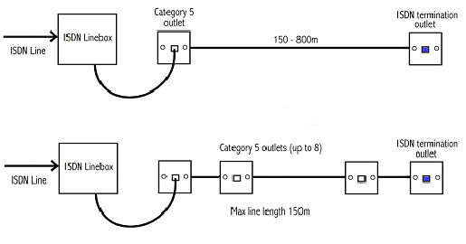
In the first diagram, a Cat 5 outlet is used with a Cat 5 patch cord as a simple way to connect the extension wiring to the Linebox. As there is only one socket on the extension wiring, this may extend as far as 800m.
In the second diagram, Cat 5 outlets are daisy-chained from the Linebox. to the ISDN termination jack. In this case the total line length must be kept below 150m.
ISDN via structured cabling
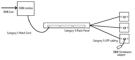
If the Linebox. is suitably located, it can be patched directly to a Category 5 Patch Panel. An ISDN Termination Adaptor must then be used to provide the necessary termination resistors.
This method will only allow one device to access the ISDN line.
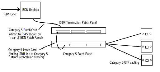
If it is necessary for several devices to be able to access the ISDN line, an ISDN Termination Patch Panel should be used. Each Panel will support up to three ISDN lines.
The panels allow the ISDN line to be connected to the rear of the panel either via a Cat 5 Patch cord to an RJ45 socket or using Cat 5 UTP cable to IDC's.
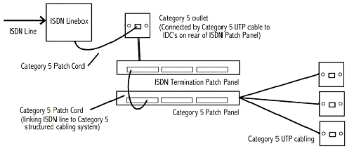
The Patch cord approach shown in the diagram above is simpler and recommended where the location of the Linebox permits.
If the Linebox is located too far from the Patch Panel or if the wire route is not suitable for a Patch Cord, a Cat 5 outlet can be located close to the Linebox and connected to the Patch Panel using Cat 5 UTP cabling.
The Cat 5 outlet is then connected to the Linebox using a standard Category 5 Patch Cord.