


The Peritel SCART Connector
The Peritel connector, or SCART connector as it is more commonly known, is an industry standard means of connecting a variety of audio-visual equipment together.
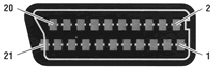
The connection consists of a 21 way female socket ( pin 21 being the metal shield of the connector ) that is fitted to most video cassette recorders ( VCR's ) and television sets these days. The pin numbering of the socket is shown below ...
The Peritel SCART connector provides for bi-directional connection of audio and composite video signals, uni-directional RGB video and a number of control signals that allow the television to control a VCR and vice-versa.
Two pieces of audio-visual equipment may be connected to each other using a single Peritel SCART connecting cable which has male plugs fitted at each end.
Connections required to link VCR to VCR, VCR to television and VCR or television to a Hi-Fi unit are described later on this page.
The Peritel SCART Connector Signals
Pin
Name
Description
1
AOR
Audio Out Right
2
AIR
Audio In Right
3
AOL
Audio Out Left + Mono
4
AGND
Audio Ground
5
BGND
RGB Blue Ground
6
AIL
Audio In Left + Mono
7
B
RGB Blue
8
SWTCH
Audio / RGB switch / 16:9
9
GGND
RGB Green Ground
10
CLKOUT
Clock Out
11
G
RGB Green
12
DATA
Data Out
13
RGND
RGB Red Ground
14
DATAGND
Data Ground
15
R
RGB Red / Chrominance
16
BLNK
Blanking Signal
17
VGND
Composite Video Ground
18
BLNKGND
Blanking Signal Ground
19
VOUT
Composite Video Out
20
VIN
Composite Video In / Luminance
21 *
SHIELD
Ground / Shield ( Chassis )
* Note that pin 21 is actually the metal housing of the Peritel SCART connector
The VCR to VCR / VCR to Television Connecting Cable
To connect a Video Cassette Recorder to another Video Cassette Recorder or a Television using composite video; two Peritel SCART plugs ( male ) should be wired one-to-one with the exception of the following pins which are crossed-over, from socket to socket , between one end and the other ...
1 to 2
2 to 1
3 to 6
6 to 3
19 to 20
20 to 19
Pins 1, 2, 3 and 6 ( Audio ) should be connected using a 4-core shielded cable with the shield connected to pin 4 at each end.
Pins 19 and 20 ( Video ) should be connected using 2-core shielded cable with the shield connected to pin 17 at each end.
Pins 7, 11 and 15 ( RGB Video ) should be connected using shielded cable with each shield connected to pins 5, 9 and 13 respectively.
Because audio and video signals are sensitive to distortion and interference it is necessary to use suitable cable for all connections to avoid cross-talk and other problems.
Given the difficulties in obtaining suitable cable, and the risk of interference which may cause degradation of picture and sound quality; it is recommended that a commercial connecting cable is purchased from a local store. These cables are not generally more expensive than home constructed ones and such a purchase will avoid all the difficulties of attempting to solder some 42 connections in, what will turn out to be, very tight connectors.
The VCR to Hi-Fi / Television to Hi-Fi Connecting Cable
Only three pins are needed take stereo audio from a video cassette recorder or television to a Hi-Fi unit using the Peritel SCART connector ...
Pin 1 - Right Audio Out
Pin 3 - Left Audio Out / Mono Audio Out
Pin 4 - Audio Ground
The connection should be made using either one, two-core shielded cable or two, single core shielded cables. The decision on which to use will normally depend on the input connection required to the Hi-Fi unit; 3 or 5-pin DIN ( one, two core cable ) or phono jacks ( two, one-core cables ).
The left audio line should be connected to pin 3 and the right audio line should be connected to pin 1. The shield of each cable should be connected to pin 4.
If the video recorder or television provides a monophonic output only; then a connection need only be made to pin 3 although the output may also be present on pin 1 on some equipment.
Because audio signals are sensitive to distortion and interference it is necessary to use suitable cable for all connections to avoid cross-talk and other problems.
If there is interference on the sound channels, such as mains hum; it may be necessary to leave the shields unconnected at the Hi-Fi inputs or leave the shield connections to pin 4 at the Peritel SCART connector off ( separating the two cable shields at that point ). Some experimentation may be necessary to remove any interference.